Free & Easy Returns
 Best Deals

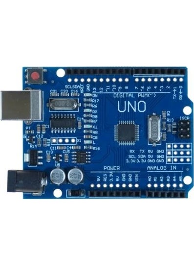
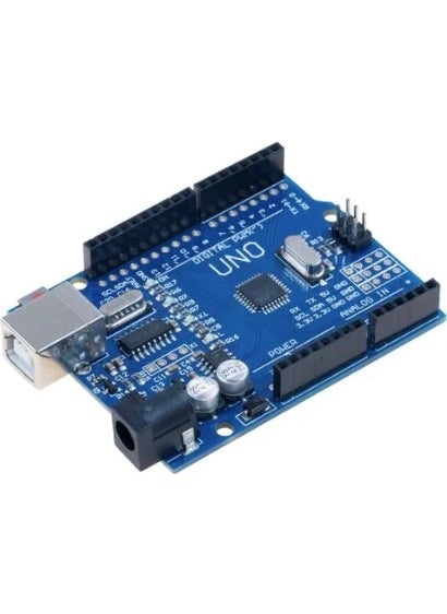
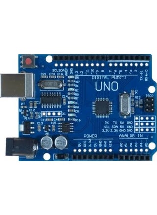
The main difference in this clone of Arduino's standard boards, Arduino Uno R3 SMD CH340 Chip, is that the programming integrated circuit (USB-Serial converter) it uses is CH340. Although there are a few minor differences from Arduino, there is no difference in terms of usage, software and compatibility of expansion cards. The difference between Arduino Uno R3 CH340 SMD and Arduino Uno Dip is that the microcontroller is separated as SMD or DIP, and the DIP type is changeable. Arduino Uno Features: Microcontroller: ATmega328 Operating Voltage: 5V Input Voltage (recommended): 7-12V Input Voltage (limit): 6-20V Digital I/O Pins: 14 (6 of them are PWM outputs) Analog Input Pins: 6 Current for Each I/O: 40 mA Current for 3.3V Output: 50 mA Flash Memory: 32 KB (ATmega328) 0.5 KB for bootloader SRAM: 2 KB (ATmega328) EEPROM: 1 KB (ATmega328) Clock Speed: 16 MHz Length: 68.6 mm Width: 53.4 mm Weight: 25 g Input and Output: All 14 digital pins on the UNO can be used as input or output. There are also 6 analog input pins. These analog input pins can also be used as digital input and output. This means that there are a total of 20 digital input and output pins on the board. The logic level of all of these pins is 5V. Each pin operates with a maximum input and output current of 40mA. In addition, some pins have different features. Special pins are as follows: Serial Communication, 0 (RX) and 1 (TX): Used to receive (RX) and send (TX) TTL Serial data. These pins are directly connected to the Atmega16u2 USB-serial converter on the board. In other words, these pins are also used when loading programs from the computer to the board or when communicating between the computer and UNO. Therefore, it is beneficial not to use these pins unless necessary to avoid errors when loading programs to the board or communicating. External Interrupt, 2 (interrupt 0) and 3 (interrupt 1): These pins can be used as rising edge, falling edge or change interrupt pins. PWM, 3, 5, 6, 9, 10 and 11: Can be used as PWM output pins with 8-bit resolution. SPI, 10 (SS), 11 (MOSI), 12 (MISO), 13 (SCK): These pins are used for SPI communication. LED, 13: There is an internal LED on the board, marked with the letter "L", connected to pin 13 on the UNO. When the pin is set to HIGH, the LED will light up, and when it is set to LOW, the LED will turn off. Analog, A0-A5: UNO has 6 analog input pins with 10-bit resolution. These pins can also be used for digital input and output. I2C, A4 or SDA pin and A5 or SCL pin: These pins are used for I2C communication. AREF: Measurement reference pin for analog inputs. Reset: This pin is set to LOW when the microcontroller is to be reset. The reset operation can also be done with the reset button on the board.