 Free & Easy Returns
 Best Deals

| Piece | 1 Piece |
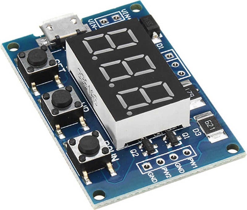
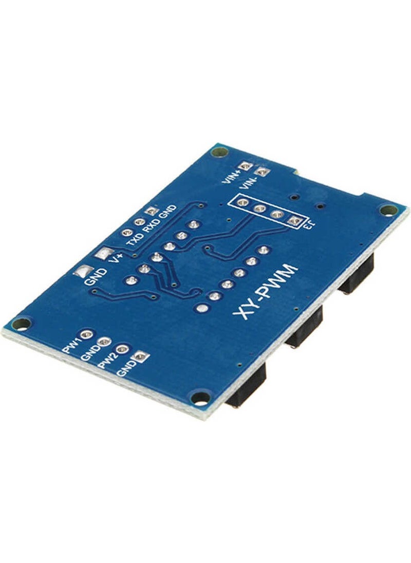
2 Channel PWM Signal Generator Module
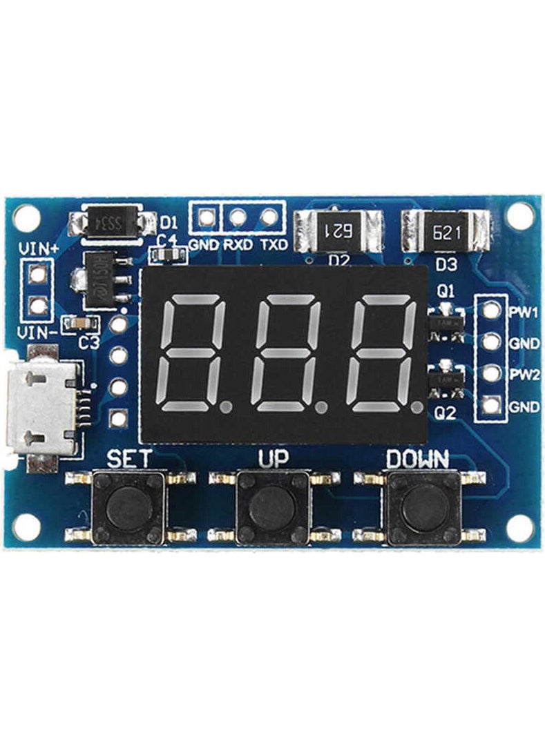
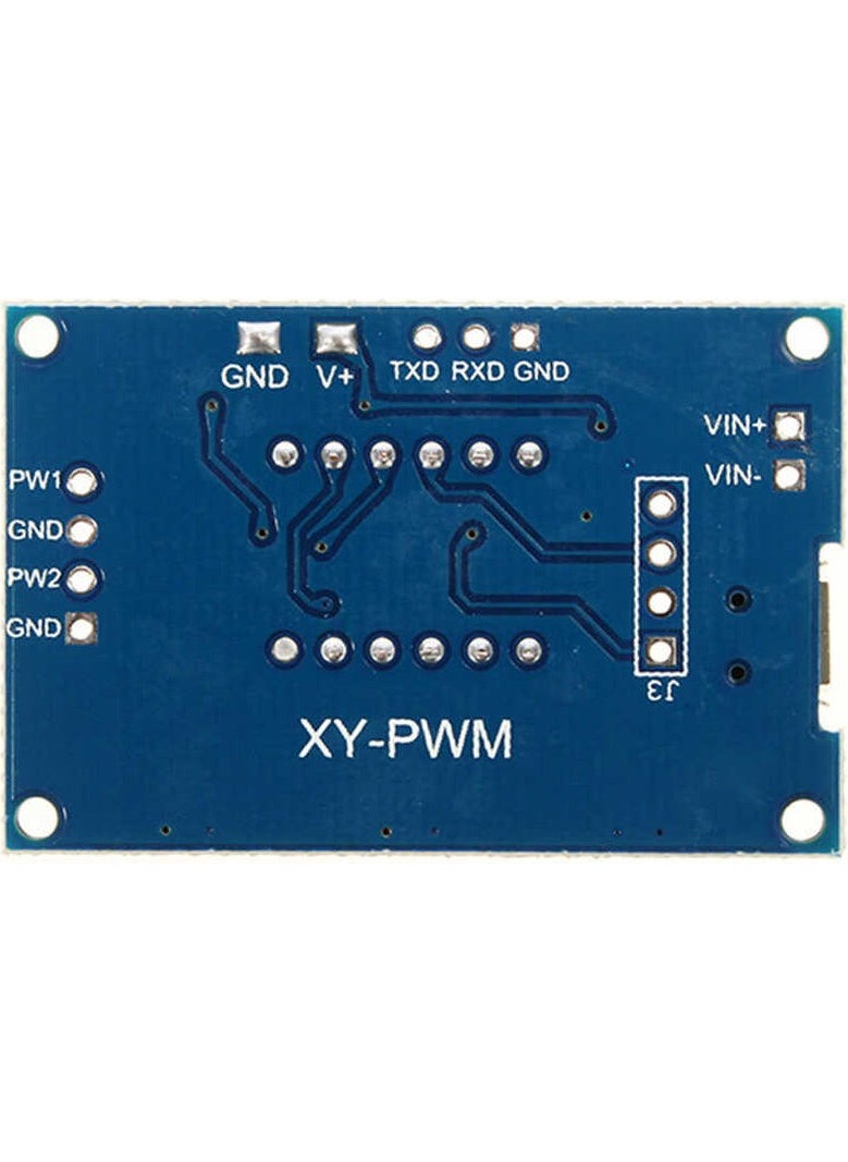
It is a 2-output card that can produce adjustable PWM signals with a frequency of 1Hz-150kHz and a duty cycle range of 0%-100%. The duty cycle and frequency of each output are adjusted with the buttons on the board. It can be powered by a DC power source in the 5-30V range or via the micro USB on it. It has high frequency accuracy. It can communicate serially with the RXD and TXD outputs on the card.
It is a product that will make your projects easier. For example, it can be used in test studies as a square wave generator, or you can use it in stepper motor control by sending signals to a motor driver.
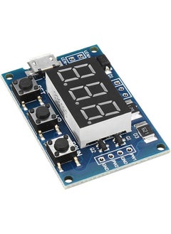
How to Adjust PWM Signal?
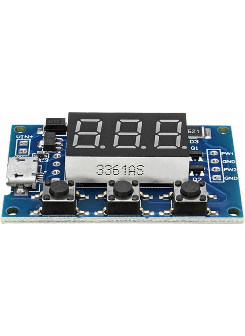
There are 3 buttons on the card: "SET", "UP" and "DOWN" respectively. When you press the “SET” button briefly, it shows the options where you can change the settings of a total of 4 parameters. These are FR1(PWM1 Frequency), dU1(PWM1 Duty Cycle), FR2(PWM2 Frequency) and dU2(PWM2 Duty Cycle) settings respectively. You need to select the parameter you want to set with the [SET] button. You can then change the value of the parameter you selected using the [UP] and [DOWN] buttons. There are 3 different frequency ranges for adjustment. (AAA:1Hz-999Hz, AA.A: 0.1 kHz – 99.9 kHz, A.A.A: 1kHz – 150 kHz) You need to press and hold the [SET] button to change the frequency range. (If it does not accept the value A, write X instead of A)
Serial Communication Parameters:
PWM Frequency Setting Commands:
PWM Duty Cycle Commands:
Technical specifications:


![/fashion-men/adidas/?sort[by]=popularity&sort[dir]=desc&limit=50](https://a.nooncdn.com/cms/pages/20240305/4ef48af441e2b44cea1673cd2e4aff67/en_dk-men-brands-01.png)
![/fashion-men/reebok/?sort[by]=popularity&sort[dir]=desc&limit=50](https://a.nooncdn.com/cms/pages/20240305/4ef48af441e2b44cea1673cd2e4aff67/en_dk-men-brands-02.png)
![/fashion-men/puma/?sort[by]=popularity&sort[dir]=desc&limit=50](https://a.nooncdn.com/cms/pages/20240305/4ef48af441e2b44cea1673cd2e4aff67/en_dk-men-brands-03.png)
![/fashion-men/jack_jones/?sort[by]=popularity&sort[dir]=desc&limit=50](https://a.nooncdn.com/cms/pages/20240305/4ef48af441e2b44cea1673cd2e4aff67/en_dk-men-brands-04.png)
![/fashion-men/american_eagle/?sort[by]=popularity&sort[dir]=desc&limit=50](https://a.nooncdn.com/cms/pages/20240305/4ef48af441e2b44cea1673cd2e4aff67/en_dk-men-brands-05.png)
![/fashion-men/tommy_hilfiger/tommy_jeans/?sort[by]=popularity&sort[dir]=desc&limit=50](https://a.nooncdn.com/cms/pages/20240305/4ef48af441e2b44cea1673cd2e4aff67/en_dk-men-brands-06.png)
![/fashion-men/calvin_klein/calvin_klein_jeans/?sort[by]=popularity&sort[dir]=desc&limit=50](https://a.nooncdn.com/cms/pages/20240305/4ef48af441e2b44cea1673cd2e4aff67/en_dk-men-brands-07.png)
![/fashion-men/seventy_five/?sort[by]=popularity&sort[dir]=desc&limit=50](https://a.nooncdn.com/cms/pages/20240305/4ef48af441e2b44cea1673cd2e4aff67/en_dk-womens-new-brands-01.png)
![/fashion-men/skechers/?sort[by]=popularity&sort[dir]=desc&limit=50](https://a.nooncdn.com/cms/pages/20240305/4ef48af441e2b44cea1673cd2e4aff67/en_dk-womens-new-brands-02.png)

![/fashion-women/adidas/?sort[by]=popularity&sort[dir]=desc&limit=50](https://a.nooncdn.com/cms/pages/20240305/4ef48af441e2b44cea1673cd2e4aff67/en_dk-women-brands-01.png)
![/fashion-women/puma/?sort[by]=popularity&sort[dir]=desc&limit=50](https://a.nooncdn.com/cms/pages/20240305/4ef48af441e2b44cea1673cd2e4aff67/en_dk-women-brands-03.png)
![/fashion-women/mango/?sort[by]=popularity&sort[dir]=desc&limit=50](https://a.nooncdn.com/cms/pages/20240305/4ef48af441e2b44cea1673cd2e4aff67/en_dk-women-brands-05.png)
![/fashion-women/guess/?sort[by]=popularity&sort[dir]=desc&limit=50](https://a.nooncdn.com/cms/pages/20240305/4ef48af441e2b44cea1673cd2e4aff67/en_dk-women-brands-09.png)
![/fashion-women/calvin_klein/calvin_klein_jeans/?sort[by]=popularity&sort[dir]=desc&limit=50](https://a.nooncdn.com/cms/pages/20240305/4ef48af441e2b44cea1673cd2e4aff67/en_dk-women-brands-07.png)
![/fashion-women/tommy_hilfiger/tommy_jeans/?sort[by]=popularity&sort[dir]=desc&limit=50](https://a.nooncdn.com/cms/pages/20240305/4ef48af441e2b44cea1673cd2e4aff67/en_dk-women-brands-06.png)
![/fashion-women/ella/?sort[by]=popularity&sort[dir]=desc&limit=50](https://a.nooncdn.com/cms/pages/20241812/en_dk-nav-brands-01.png)
![/fashion-women/skechers/?sort[by]=popularity&sort[dir]=desc&limit=50](https://a.nooncdn.com/cms/pages/20241812/en_dk-nav-brands-02.png)
![/fashion-women/american_eagle/?sort[by]=popularity&sort[dir]=desc&limit=50](https://f.nooncdn.com/cms/pages/20250317/womens/en_dk-nav-brands-09.png)

![/fashion/view-all-kids-clothing/adidas/?sort[by]=popularity&sort[dir]=desc&limit=50](https://a.nooncdn.com/cms/pages/20240911/nav-web/en_mb_uae_brand-02.png)
![/fashion/view-all-kids-clothing/puma/?sort[by]=popularity&sort[dir]=desc&limit=50](https://a.nooncdn.com/cms/pages/20240911/nav-web/en_mb_uae_brand-04.png)
![/fashion/view-all-kids-clothing/nike/?sort[by]=popularity&sort[dir]=desc&limit=50](https://a.nooncdn.com/cms/pages/20240911/nav-web/en_mb_uae_brand-01.png)
![/fashion/view-all-kids-clothing/disney/disney_minnie_mouse/disney_frozen/disney_princess/disney_mickey_mouse/disney_baby/?sort[by]=popularity&sort[dir]=desc&limit=50](https://a.nooncdn.com/cms/pages/20240911/nav-web/en_mb_uae_brand-03.png)
![/fashion/view-all-kids-clothing/tommy_hilfiger/tommy_jeans/?sort[by]=popularity&sort[dir]=desc&limit=50](https://a.nooncdn.com/cms/pages/20240911/nav-web/en_mb_uae_brand-07.png)
![/fashion/view-all-kids-clothing/calvin_klein/calvin_klein_jeans/?sort[by]=popularity&sort[dir]=desc&limit=50](https://a.nooncdn.com/cms/pages/20240911/nav-web/en_mb_uae_brand-08.png)
![/fashion/view-all-kids-clothing/mothercare/?sort[by]=popularity&sort[dir]=desc&limit=50](https://a.nooncdn.com/cms/pages/20240911/nav-web/en_mb_uae_brand-06.png)

![/fashion/view-all-kids-clothing/kappa/?sort[by]=popularity&sort[dir]=desc&limit=50](https://a.nooncdn.com/cms/pages/20240911/nav-web/en_mb_uae_brand-10.png)
![/fashion/view-all-kids-clothing/new_balance/?sort[by]=popularity&sort[dir]=desc&limit=50](https://a.nooncdn.com/cms/pages/20240911/nav-web/en_mb_uae_brand-11.png)


![/baby-products/momcozy/?f[partner][]=p_9404&sort[by]=popularity&sort[dir]=desc&limit=50&page=1&isCarouselView=false&av=0](https://a.nooncdn.com/cms/pages/20241031/navrev-baby/en_uae_dk-nav-04.png)


![/music-movies-and-tv-shows/musical-instruments-24670/pianos-keyboards-synthesizers/roland/?sort[by]=popularity&sort[dir]=desc&limit=50&page=1&isCarouselView=false](https://f.nooncdn.com/cms/pages/20250407/books-nav/en_uae_dk-nav-brands-05.png)
![/music-movies-and-tv-shows/musical-instruments-24670/pianos-keyboards-synthesizers/mike_music/?sort[by]=popularity&sort[dir]=desc&limit=50&page=1&isCarouselView=false](https://f.nooncdn.com/cms/pages/20250407/books-nav/en_ksa_dk-nav-brands-04.png)


